OSPF (Open Shortest Path First)
Overview
Section titled “Overview”OSPF (Open Shortest Path First) is a link-state IGP used to distribute routing information within a single autonomous system (AS).
OSPF uses a series of message types including Hello, Update, and Acks. The payload of these messages are called LSAs (Link-State Advertisements). These LSAs have multiple types, each of which provide different information according to their type, but almost always related to network routes. For example, one LSA may simply tell other routers what networks it has reachability to, while another may be telling other routers on a broadcast segment that it is there.
OSPF uses Dijkstra’s Shortest Path First (SPF) algorithm to calculate the best path to every destination, considering the main metric which is the summation of all egress interface’s Cost, being a manually configured reference bandwidth divided by the interfaces actual bandwidth.
About This Document
Section titled “About This Document”This document is designed to be read top down as a full OSPF lesson. The reader is walked from the world view (areas, roles), into how routers cooperate (adjacency, LSDB), then into how routes are chosen (SPF), then into operational topics (stubs, virtual links, authentication, configuration).
OSPFv3 is covered after OSPFv2. All previous info is based on OSPFv2.
The full OSPF wire format (packet header, packet types, byte layouts) is provided at the end of this document as a reference appendix. It is not required for conceptual understanding.
This document uses the ABNF Specification (RFC 5234) to define protocol structures. The syntax for a repeating field uses an asterisk (*) meaning “zero or more”.
The OSPF Hierarchy
Section titled “The OSPF Hierarchy”Why OSPF Has Areas
Section titled “Why OSPF Has Areas”A single OSPF area is bounded by its LSDB, every router in the area must hold an identical copy. As the area grows, three pressures appear:
- LSDB size scales with the number of links and routers.
- SPF runtime scales worse than linearly with LSDB size.
- Flooding domain grows, meaning any link flap is felt by every router in the area.
OSPF solves this with hierarchy: split the AS into smaller areas connected by a central backbone. Each area runs SPF locally, while inter-area routes are summarized at the boundary.
Area 0 (Backbone)
Section titled “Area 0 (Backbone)”Every OSPF AS has a single backbone area identified as Area 0 (or 0.0.0.0 in dotted-decimal). All non-backbone areas must connect to Area 0, either directly or through a virtual link.
This rule prevents routing loops by forcing all inter-area traffic to transit the backbone.
Router Roles
Section titled “Router Roles”Internal Router
Section titled “Internal Router”- All OSPF-enabled interfaces sit in a single non-backbone area.
- Originates only Router-LSAs (Type 1) into its area.
Backbone Router
Section titled “Backbone Router”- At least one OSPF-enabled interface in Area 0.
- May also be an ABR if it has interfaces in non-backbone areas.
Area Border Router (ABR)
Section titled “Area Border Router (ABR)”- Sits between Area 0 and one or more non-backbone areas.
- Maintains a separate LSDB per area it touches. Be careful, this can overburden the router if it touches many areas.
- Originates Type 3 Summary-LSAs into adjacent areas to describe inter-area destinations.
- Sets the B bit in its Router-LSA.
Autonomous System Boundary Router (ASBR)
Section titled “Autonomous System Boundary Router (ASBR)”- Redistributes routes from outside OSPF (other routing protocols, static routes,
default-information originate) into OSPF. - Originates Type 5 AS-External-LSAs (or Type 7 inside an NSSA).
- Sets the E bit in its Router-LSA.
A single router can play multiple roles simultaneously. For example, a backbone router that is also an ABR and an ASBR.
Route Types
Section titled “Route Types”Each route in the OSPF routing table is tagged by how it entered the LSDB:
Code Description Origin______________________________________________________________O Intra-area Router/Network-LSAO IA Inter-area Type 3 Summary-LSAO E1 External Type 1 (metric increases) Type 5O E2 External Type 2 (metric fixed) Type 5 (DEFAULT)O N1 NSSA External Type 1 Type 7O N2 NSSA External Type 2 Type 7Ranking and tie-breaking for these route types is covered in the SPF Calculation section.
Router-ID Selection
Section titled “Router-ID Selection”The router-id [ip] command uniquely identifies a router within an OSPF process. The Router-ID is in IPv4 format but does not need to be reachable, it is just an identifier.
The Router-ID is selected based on:
- Manually configured with
router-id. - Highest IP address on an active loopback interface.
- Highest IP address on an active physical interface.
router ospf 1 router-id 1.1.1.1The Router-ID is selected once when the OSPF process starts and is not re-evaluated automatically when interfaces change. To force re-selection, use clear ip ospf process.
Router-IDs must be unique across the OSPF AS. Duplicate Router-IDs cause adjacency formation failures, LSDB corruption, and routing loops.
Loopback interfaces are preferred over physical interfaces because they are always up unless explicitly shut down. This makes the Router-ID stable across physical link failures.
Network Types
Section titled “Network Types”The OSPF network type, set per interface, governs three things:
- Whether a DR/BDR is elected on the segment.
- Default Hello and Dead timer values.
- How the segment is represented in LSAs (specifically, whether a Network-LSA is generated).
The ip ospf network [broadcast | point-to-point | non-broadcast | point-to-multipoint | point-to-multipoint non-broadcast] command sets the OSPF network type on an interface. Loopback type is automatic on loopback interfaces.
Broadcast
Section titled “Broadcast”- Default on Ethernet (GigabitEthernet, FastEthernet, TenGigabitEthernet, etc).
- Elects DR/BDR.
- Hellos sent via Multicast 224.0.0.5.
- Hello timer: 10 seconds / Dead timer: 40 seconds.
- Segment is described in the LSDB by a Network-LSA (Type 2) originated by the DR.
Point-to-Point
Section titled “Point-to-Point”- Default on HDLC, PPP, GRE tunnels, and sub-interfaces.
- No DR/BDR (only two routers on the link).
- Hellos sent via Multicast 224.0.0.5.
- Hello timer: 10 seconds / Dead timer: 40 seconds.
- Both routers go directly to FULL with each other.
Non-Broadcast (NBMA)
Section titled “Non-Broadcast (NBMA)”- Default on Frame Relay and ATM main interfaces.
- Elects DR/BDR.
- Hellos sent via Unicast (neighbors must be manually defined).
- Hello timer: 30 seconds / Dead timer: 120 seconds.
Point-to-Multipoint
Section titled “Point-to-Multipoint”- No DR/BDR.
- Treats the segment as a collection of point-to-point links from each spoke to the hub.
- Hellos sent via Multicast 224.0.0.5.
- Hello timer: 30 seconds / Dead timer: 120 seconds.
Point-to-Multipoint Non-Broadcast
Section titled “Point-to-Multipoint Non-Broadcast”- No DR/BDR.
- Manual neighbor configuration with Unicast Hellos.
- Useful on DMVPN phase 1/2 deployments.
Loopback
Section titled “Loopback”- Always advertised as a /32 host route regardless of the interface’s actual mask.
- Never forms adjacencies (no Hellos are sent on loopbacks).
Adjacency Process
Section titled “Adjacency Process”When you connect two OSPF routers, they transition through these eight distinct states sequentially:
- Down
- Attempt (NBMA networks only)
- Init
- 2-Way
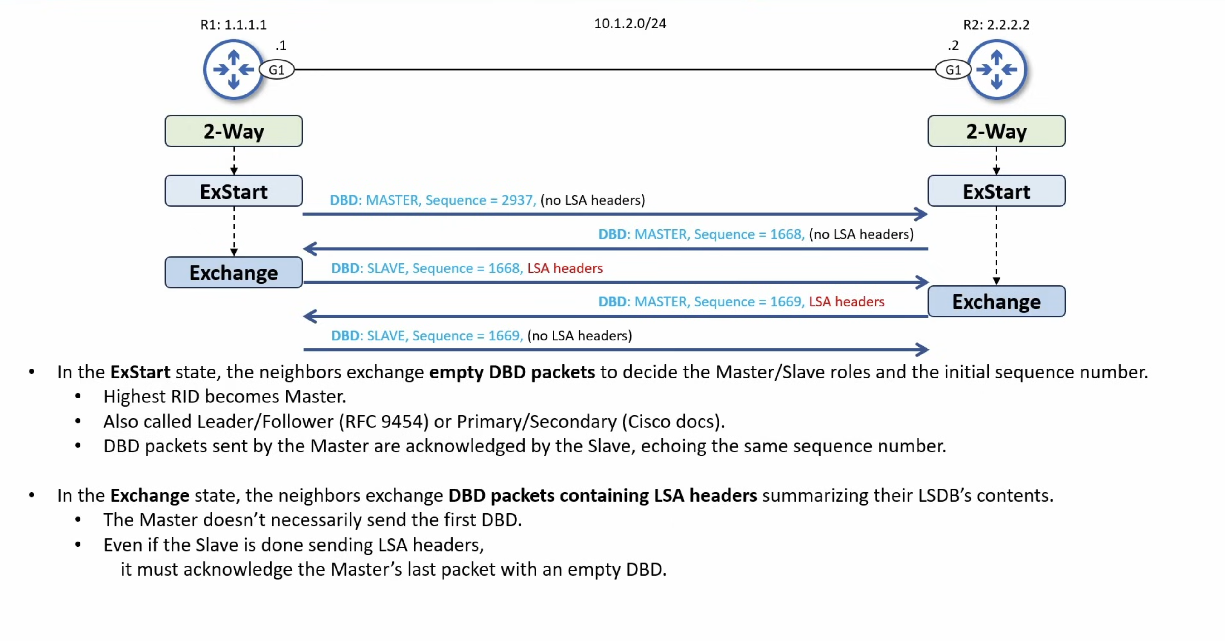
- Exstart
- Exchange
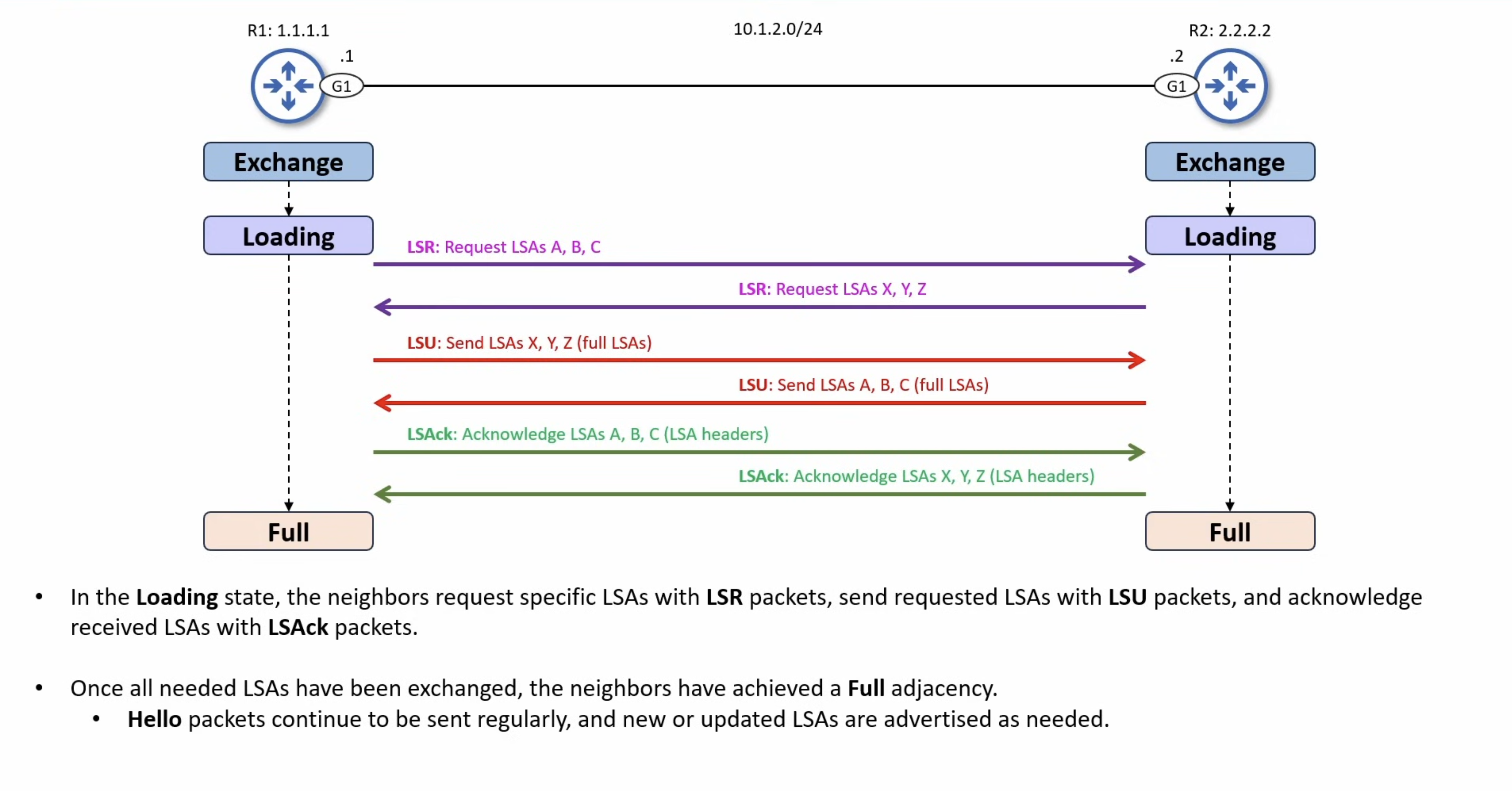
- Loading
- Full

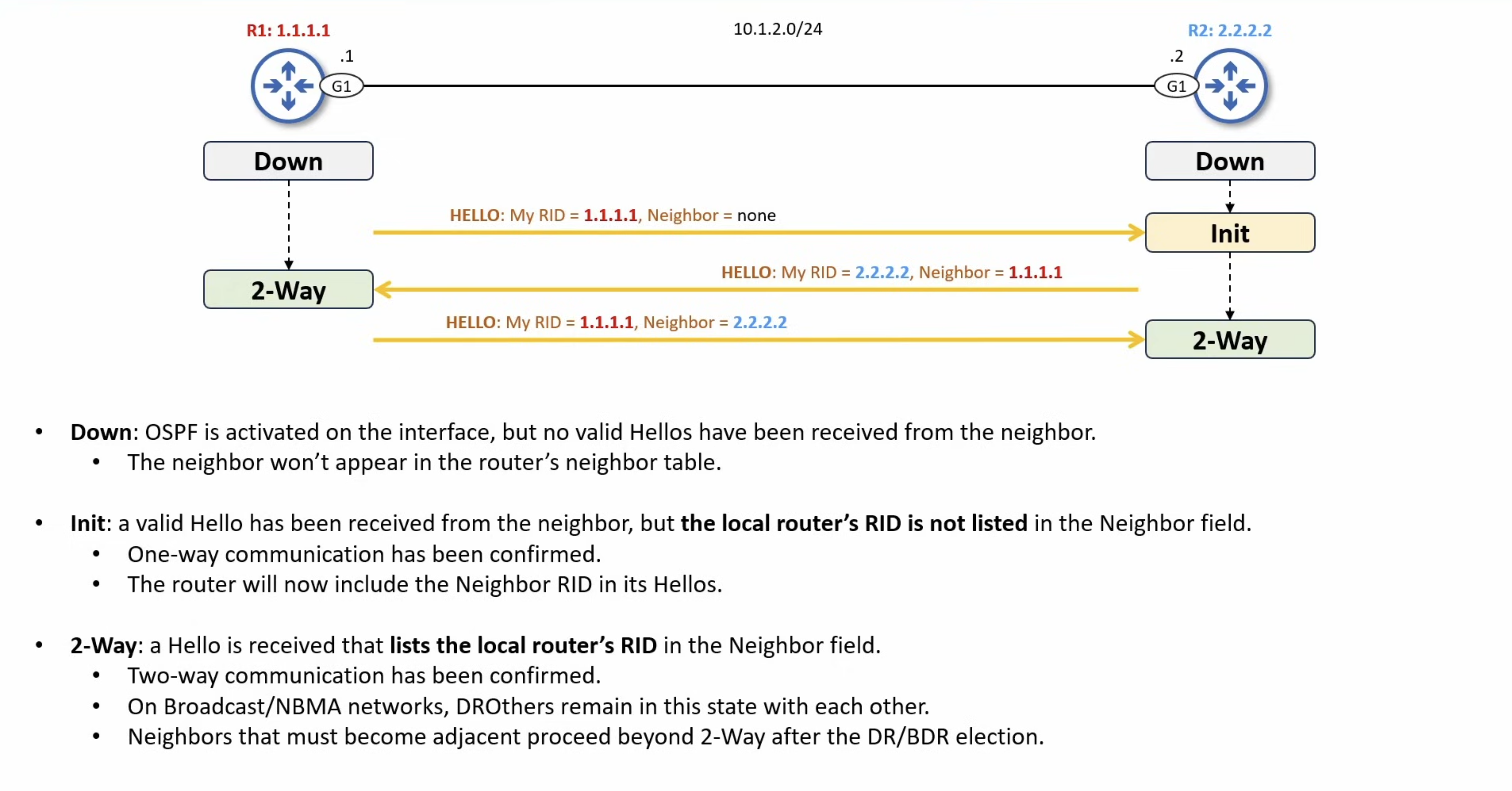
ROUTER A STATE                                               ROUTER B STATE==============                                               ==============
 [ DOWN ]                                                       [ DOWN ]    |                                                              |    |--- (Hello: My ID is 1.1.1.1) ------------------------------->|    |    Neighbors Seen: [None]                                    |    |                                                              V [ DOWN ]                                                       [ INIT ]    |                                                              |    |<-- (Hello: My ID is 2.2.2.2) --------------------------------|    |    Neighbors Seen: 1.1.1.1                                   |    V                                                              | [ 2-WAY ]                                                         |    |                                                              |    |                                                              |    |--- (Hello: My ID is 1.1.1.1) ------------------------------->|    |    Neighbors Seen:  2.2.2.2                                  |    |                                                              V [ 2-WAY ]                                                      [ 2-WAY ][ EXSTART ]                                                    [ EXSTART ]    |                                                              |  |----- (DBD: Seq=100, I'm Master, More=1) -------------------->|  |<---- (DBD: Seq=500, I'm Master, More=1) ---------------------|  |                                  (I have higher Router ID!)  |  |  (A surrenders, assumes B as Master)                         |  |                                                              |  V                                                              V[ EXCHANGE ]                                                 [ EXCHANGE ]    |                                                              |  |--- (DBD: Seq=500, I'm Slave, [LSA Headers A], More=1) ------>|  |      (A sends its summary list)                              |  |                                                              |  |<-- (DBD: Seq=501, I'm Master, [LSA Headers B], More=0) ------|  |                           (B sends its summary list)         |    |                                                              |  |--- (DBD: Seq=501, I'm Slave, Empty DBD, More=0) ------------>|  |      (A acknowledges B's final packet, aka More=0)           |    |                                                              |  V                                                              V[ LOADING ]                                                   [ LOADING ]    |                                                              |  |--- (LSR: "Send me full info for LSA X") -------------------->|  |                                                              |  |<-- (LSU: [Full LSA X Data Body Payload]) --------------------|  |                                 (B sends the missing cargo)  |  |                                                              |  |--- (LSAck: "Got LSA X, thank you") ------------------------->|  |                                                              |  V                                                              V [ FULL ]                                                      [ FULL ]
Neighbor Requirements
Section titled “Neighbor Requirements”For two routers to progress from Down through to FULL, the following parameters must match between them:
- Area ID.
- Subnet mask (on multi-access segments only, point-to-point links ignore the mask).
- Hello and Dead timer values.
- Authentication type and key.
- Stub area flag in Hello Options.
- MTU (compared during the DBD exchange, not from Hellos).
A mismatch on any of the above will prevent the adjacency from progressing past whichever stage validates that parameter.
Timer Configuration
Section titled “Timer Configuration”The ip ospf hello-interval [seconds] command sets the time between Hello packets on an interface.
The ip ospf dead-interval [seconds] command sets how long a router waits before declaring a silent neighbor down. Cisco’s default Dead = 4 × Hello.
interface GigabitEthernet0/0 ip ospf hello-interval 5 ip ospf dead-interval 20The ip ospf dead-interval minimal hello-multiplier [3-20] command enables sub-second Hellos, where the Dead interval stays at 1 second and Hellos are sent at 1/multiplier second intervals.
MTU Mismatch Workaround
Section titled “MTU Mismatch Workaround”If two routers have different interface MTUs, the DBD exchange will hang in the Exstart or Exchange state.
The ip ospf mtu-ignore command tells the router to skip the MTU check during DBD negotiation. Use this only when you cannot fix the MTU mismatch at the source.
interface GigabitEthernet0/0 ip ospf mtu-ignoreDR/BDR Election
Section titled “DR/BDR Election”On multi-access segments (broadcast, NBMA) with N routers, full-mesh adjacencies would require N(N-1)/2 LSDB exchanges. The DR/BDR mechanism collapses this into a hub-and-spoke: every router only forms a FULL adjacency with the DR and BDR, and the DR is responsible for originating the Network-LSA (Type 2) that describes the segment.
Routers that are neither DR nor BDR on a segment are called DROther routers. DROther-to-DROther neighbor relationships stop at the 2-Way state, they see each other in Hellos but never synchronize LSDBs directly.
Multicast Addresses
Section titled “Multicast Addresses”- 224.0.0.5 (AllSPFRouters): used by DR/BDR to send LSU and LSAck packets to every router on the segment.
- 224.0.0.6 (AllDRouters): used by DROther routers to send LSU and LSAck packets to only the DR and BDR.
Election Rules
Section titled “Election Rules”- Highest OSPF interface priority (range 0-255, default 1).
- Highest OSPF Router-ID as the tiebreaker.
A priority of 0 makes a router ineligible to ever become DR or BDR on that segment.
The ip ospf priority [0-255] command sets the OSPF interface priority. This is the primary lever for influencing DR/BDR placement.
interface GigabitEthernet0/0 ip ospf priority 100Non-Preemption
Section titled “Non-Preemption”DR/BDR roles are non-preemptive. Once elected, a DR/BDR keeps its role until the OSPF process resets or the router goes down, even if a higher-priority router joins the segment later.
When the DR fails:
- The BDR is promoted to DR automatically.
- A new BDR is elected from the remaining DROthers using the standard rules.
To force a re-election (for example, after raising a priority), use
clear ip ospf processon the routers involved.
Adjacency State on a Broadcast Segment
Section titled “Adjacency State on a Broadcast Segment”Neighbor Pair Final State__________________________________DR <-> BDR FULLDR <-> DROther FULLBDR <-> DROther FULLDROther <-> DROther 2-WayThis is why the Adjacency Process state diagram above shows two routers progressing cleanly to FULL, it depicts a Point-to-Point segment. On a broadcast segment, only adjacencies that involve the DR or BDR reach FULL.
Terminology
Section titled “Terminology”- A neighbor is any router that has reached the 2-Way state.
- An adjacency is a neighbor that has reached the FULL state.
These terms are commonly used interchangeably in casual writing, but the distinction matters during troubleshooting.
LSAs & The LSDB
Section titled “LSAs & The LSDB”LSA Header
Section titled “LSA Header”All LSAs (Link State Advertisements) begin with a common 20 byte header. This header contains enough information to uniquely identify the LSA (LS type, Link State ID, and Advertising Router). Multiple instances of the LSA may exist in the routing domain at the same time. It is then necessary to determine which instance is more recent. This is accomplished by examining the LS age, LS sequence number and LS checksum fields that are also contained in the LSA header.
OSPF LSA Header0 1 2 30 1 2 3 4 5 6 7 8 9 0 1 2 3 4 5 6 7 8 9 0 1 2 3 4 5 6 7 8 9 0 1+-+-+-+-+-+-+-+-+-+-+-+-+-+-+-+-+-+-+-+-+-+-+-+-+-+-+-+-+-+-+-+-+| ...header + message... |+-+-+-+-+-+-+-+-+-+-+-+-+-+-+-+-+-+-+-+-+-+-+-+-+-+-+-+-+-+-+-+-+| LS Age | Options | LS type |+-+-+-+-+-+-+-+-+-+-+-+-+-+-+-+-+-+-+-+-+-+-+-+-+-+-+-+-+-+-+-+-+| Link State ID |+-+-+-+-+-+-+-+-+-+-+-+-+-+-+-+-+-+-+-+-+-+-+-+-+-+-+-+-+-+-+-+-+| Advertising Router |+-+-+-+-+-+-+-+-+-+-+-+-+-+-+-+-+-+-+-+-+-+-+-+-+-+-+-+-+-+-+-+-+| LS Sequence Number |+-+-+-+-+-+-+-+-+-+-+-+-+-+-+-+-+-+-+-+-+-+-+-+-+-+-+-+-+-+-+-+-+| LS Checksum | Length |+-+-+-+-+-+-+-+-+-+-+-+-+-+-+-+-+-+-+-+-+-+-+-+-+-+-+-+-+-+-+-+-+LS Age
- The time in seconds since the LSA was originated.
Options
- The optional capabilities supported by the described portion of the routing domain.
LS Type
- The type of the contained LSA.
- Each LSA type has a separate advertisement body/payload format.
LS Type Description___________________________________1 Router-LSAs2 Network-LSAs3 Summary-LSAs (IP Network)4 Summary-LSAs (ASBR Location)5 AS-external-LSAsLink State ID
- This field identifies the portion of the environment that is being described by the LSA.
- The contents of this field depend on the LSA’s LS type.
- For example, in Network-LSAs (2) the Link State ID is set to the IP interface address of the network’s Designated Router (from which the Network Address can be derived).
Advertising Router
- The Router ID of the router that originated the LSA.
- For example, in Network-LSAs (2) this field is equal to the Router ID of the network’s Designated Router.
LS Sequence Number
- Detects old or duplicate LSAs.
- Successive instances of an LSA are given successive LS sequence numbers.
LS Checksum
- The checksum (Fletcher) of the complete contents of the LSA, including the LSA header but excluding the LS age field.
- Why exclude the LSA Age field? Because the age constantly changes as the packet moves from router to router, the checksum would break if it included those 2 bytes.
Length
- The length in bytes of the LSA (including the 20-byte header).
- This tells the receiving router how long the entire LSA is.
LSA Types
Section titled “LSA Types”There are 5 types of LSAs, each beginning with a 20-byte LSA header, followed by the specific type’s body/payload.
Router-LSAs
Section titled “Router-LSAs”Each router in an area originates a router-LSA.
The LSA describes the state and cost of the router’s links (i.e., interfaces) to the area. All of the router’s links to the area must be described in a single router-LSA.
OSPF Router-LSA0 1 2 30 1 2 3 4 5 6 7 8 9 0 1 2 3 4 5 6 7 8 9 0 1 2 3 4 5 6 7 8 9 0 1+-+-+-+-+-+-+-+-+-+-+-+-+-+-+-+-+-+-+-+-+-+-+-+-+-+-+-+-+-+-+-+-+| ...ospf_header + message + lsa_header... |+-+-+-+-+-+-+-+-+-+-+-+-+-+-+-+-+-+-+-+-+-+-+-+-+-+-+-+-+-+-+-+-+| 0 |V|E|B| 0 | # Links |+-+-+-+-+-+-+-+-+-+-+-+-+-+-+-+-+-+-+-+-+-+-+-+-+-+-+-+-+-+-+-+-+| Link ID |+-+-+-+-+-+-+-+-+-+-+-+-+-+-+-+-+-+-+-+-+-+-+-+-+-+-+-+-+-+-+-+-+| Link Data |+-+-+-+-+-+-+-+-+-+-+-+-+-+-+-+-+-+-+-+-+-+-+-+-+-+-+-+-+-+-+-+-+| Type | # TOS | Metric |+-+-+-+-+-+-+-+-+-+-+-+-+-+-+-+-+-+-+-+-+-+-+-+-+-+-+-+-+-+-+-+-+| * above 3 fields |In Router-LSAs, the Link State ID field in the OSPF Packet Header is set to the router’s OSPF Router ID.
Router-LSAs are flooded throughout a single area only.
Bit V
- When set, the router is an endpoint of one or more fully adjacent virtual links having the described area as Transit area (V is for virtual link endpoint).
Bit E
- When set, the router is an AS boundary router (E is for external).
Bit B
- When set, the router is an area border router (B is for border).
# Links
- The number of router links described in this LSA.
- This must be the total collection of router links (i.e., interfaces) to the area.
The following fields are used to describe each router link (i.e., interface). Each router link is typed (see the below Type field).
The Type field indicates the kind of link being described. It may be a link to a transit network, to another router or to a stub network. The values of all the other fields describing a router link depend on the link’s Type.
Type
- A quick description of the router link.
- One of the following.
- Note that host routes are classified as links to stub networks with network mask of 0xffffffff.
Type Description__________________________________________________1 Point-to-point connection to another router2 Connection to a transit network3 Connection to a stub network4 Virtual linkLink ID
- Value depends on the link’s Type.
- Identifies the object that this router link connects to.
- When connecting to an object that also originates an LSA (i.e., another router or a transit network) the Link ID is equal to the neighboring LSA’s Link State ID. This provides the key for looking up the neighboring LSA in the link state database during the routing table calculation.
Type Link ID______________________________________1 Neighboring router's Router ID2 IP address of Designated Router3 IP network/subnet number4 Neighboring router's Router IDLink Data
- Value again depends on the link’s Type field.
- For connections to stub networks, Link Data specifies the network’s IP address mask.
- For unnumbered point-to-point connections, it specifies the interface’s MIB-II ifIndex value. For the other link types it specifies the router interface’s IP address. This latter piece of information is needed during the routing table build process, when calculating the IP address of the next hop.
# TOS
- The number of different TOS metrics given for this link, not counting the required link metric.
Metric
- The cost of using this router link.
Additional TOS-specific information may also be included, for backward compatibility with previous versions of the OSPF specification.
Network-LSAs
Section titled “Network-LSAs”A Network-LSA is originated for each broadcast and NBMA network in the area which supports two or more routers. The Network-LSA is originated by the network’s Designated Router. The LSA describes all routers attached to the network, including the Designated Router itself. The LSA’s Link State ID field lists the IP interface address of the Designated Router.
OSPF Network-LSA0 1 2 30 1 2 3 4 5 6 7 8 9 0 1 2 3 4 5 6 7 8 9 0 1 2 3 4 5 6 7 8 9 0 1+-+-+-+-+-+-+-+-+-+-+-+-+-+-+-+-+-+-+-+-+-+-+-+-+-+-+-+-+-+-+-+-+| ...ospf_header + message + lsa_header... |+-+-+-+-+-+-+-+-+-+-+-+-+-+-+-+-+-+-+-+-+-+-+-+-+-+-+-+-+-+-+-+-+| Network Mask |+-+-+-+-+-+-+-+-+-+-+-+-+-+-+-+-+-+-+-+-+-+-+-+-+-+-+-+-+-+-+-+-+| * Attached Router |+-+-+-+-+-+-+-+-+-+-+-+-+-+-+-+-+-+-+-+-+-+-+-+-+-+-+-+-+-+-+-+-+Network Mask
- The IP address subnet mask for the network.
- Remember: the Link State ID field in the LSA Header is the network address.
Attached Router
- The Router IDs of each of the routers attached to the network.
- Repeated as a list for every Attached Router.
Summary-LSAs
Section titled “Summary-LSAs”These LSAs are originated by area border routers. Summary-LSAs describe inter-area destinations.
Type 3 summary-LSAs are used when the destination is an IP network. In this case the LSA’s Link State ID field is an IP network number (if necessary, the Link State ID can also have one or more of the network’s “host” bits set.
When the destination is an AS boundary router, a Type 4 summary-LSA is used, and the Link State ID field is the AS boundary router’s OSPF Router ID.
Other than the difference in the Link State ID field, the format of Type 3 and 4 summary-LSAs is identical.
OSPF Summary-LSA0 1 2 30 1 2 3 4 5 6 7 8 9 0 1 2 3 4 5 6 7 8 9 0 1 2 3 4 5 6 7 8 9 0 1+-+-+-+-+-+-+-+-+-+-+-+-+-+-+-+-+-+-+-+-+-+-+-+-+-+-+-+-+-+-+-+-+| ...ospf_header + message + lsa_header... |+-+-+-+-+-+-+-+-+-+-+-+-+-+-+-+-+-+-+-+-+-+-+-+-+-+-+-+-+-+-+-+-+| Network Mask |+-+-+-+-+-+-+-+-+-+-+-+-+-+-+-+-+-+-+-+-+-+-+-+-+-+-+-+-+-+-+-+-+| 0 | Metric |+-+-+-+-+-+-+-+-+-+-+-+-+-+-+-+-+-+-+-+-+-+-+-+-+-+-+-+-+-+-+-+-+| * above 2 fields |For stub areas, Type 3 Summary-LSAs can also be used to describe a (per-area) default route. Default summary routes are used in stub areas instead of flooding a complete set of external routes. When describing a default summary route, the summary-LSA’s Link State ID is always set to DefaultDestination (0.0.0.0) and the Network Mask is set to 0.0.0.0.
Network Mask
- For Type 3 Summary-LSAs, this indicates the destination network’s IP address subnet mask.
- This field is not meaningful and must be zero for Type 4 summary-LSAs.
Metric
- The cost of this route.
- Expressed in the same units as the interface costs in the router-LSAs.
AS-External-LSAs
Section titled “AS-External-LSAs”These LSAs are originated by AS boundary routers, and describe destinations external to the AS. AS-external-LSAs usually describe a particular external destination.
AS-external-LSAs are also used to describe a default route. When describing a default route, the Link State ID is always set to DefaultDestination (0.0.0.0) and the Network Mask is set to 0.0.0.0.
OSPF AS-External-LSAs0 1 2 30 1 2 3 4 5 6 7 8 9 0 1 2 3 4 5 6 7 8 9 0 1 2 3 4 5 6 7 8 9 0 1+-+-+-+-+-+-+-+-+-+-+-+-+-+-+-+-+-+-+-+-+-+-+-+-+-+-+-+-+-+-+-+-+| ...ospf_header + message + lsa_header... |+-+-+-+-+-+-+-+-+-+-+-+-+-+-+-+-+-+-+-+-+-+-+-+-+-+-+-+-+-+-+-+-+| Network Mask |+-+-+-+-+-+-+-+-+-+-+-+-+-+-+-+-+-+-+-+-+-+-+-+-+-+-+-+-+-+-+-+-+|E| 0 | Metric |+-+-+-+-+-+-+-+-+-+-+-+-+-+-+-+-+-+-+-+-+-+-+-+-+-+-+-+-+-+-+-+-+| Forwarding Address |+-+-+-+-+-+-+-+-+-+-+-+-+-+-+-+-+-+-+-+-+-+-+-+-+-+-+-+-+-+-+-+-+| External Route Tag |+-+-+-+-+-+-+-+-+-+-+-+-+-+-+-+-+-+-+-+-+-+-+-+-+-+-+-+-+-+-+-+-+Network Mask
- The IP address mask for the advertised destination.
Bit E
- The type of external metric.
- If bit E is set, the metric specified is a Type 2 external metric.
- If bit E is set to zero, the specified metric is a Type 1 external metric.
Metric
- The cost of this route.
- Interpretation depends on the external type indication (bit E above).
Forwarding Address
- Data traffic for the advertised destination will be forwarded to this address.
External Route Tag
- A 32-bit field attached to each external route.
- This is not used by the OSPF protocol itself.
LSA Lifecycle
Section titled “LSA Lifecycle”Each LSA is refreshed every 30 minutes by its originator. The MaxAge timer is 60 minutes. An LSA that is not refreshed before MaxAge is flushed from the LSDB and SPF re-runs without it.
SPF Calculation
Section titled “SPF Calculation”OSPF’s metric is cost, a 16-bit value carried in the Metric field of Router-LSAs and Summary-LSAs.
Interface Cost
Section titled “Interface Cost”interface_cost = reference_bandwidth / interface_bandwidth- Default reference bandwidth: 100,000 Kbps (100 Mbps).
- Minimum cost: 1. Anything that would round below 1 is clamped to 1.
- Loopback cost: always 1.
By default, every interface at 100 Mbps and above gets the same cost of 1, which is almost never what you want in a modern network.
The OSPF Cost to a destination is the sum of the cost of every egress interface along the path.
Bandwidth, like Delay, is used only for metric calculation. It does not affect data plane forwarding.
Changing Cost
Section titled “Changing Cost”Three knobs, in increasing order of specificity:
The auto-cost reference-bandwidth [mbps] command changes the reference bandwidth for the entire OSPF process.
router ospf 1 auto-cost reference-bandwidth 100000The bandwidth [kbps] interface command changes the interface’s reported bandwidth, which feeds the cost formula.
The ip ospf cost [cost] interface command overrides cost entirely on a single interface, ignoring the formula.
interface GigabitEthernet0/0 ip ospf cost 10Configure the reference bandwidth higher than your fastest link, 100× the fastest is a common rule of thumb. Set this consistently across every router in the AS, since mismatched reference bandwidths produce asymmetric routing.
Running SPF
Section titled “Running SPF”Every router roots the SPF tree at its own Router-LSA and walks the graph built from the LSDB, summing the cost of egress interfaces along each path. Because every router in the area holds an identical LSDB, every router computes the same shortest-path tree from its own perspective.
The three main steps to determine the best path:
- Become neighbors with other routers connected to the same segment.
- Exchange LSAs with neighboring routers until the LSDB is synchronized.
- Run SPF against the LSDB and install the best route to each destination in the routing table.
Route Preference
Section titled “Route Preference”When multiple LSAs describe the same destination, OSPF prefers them in this order, regardless of metric:
- Intra-area (O).
- Inter-area (O IA).
- External Type 1 (O E1): external cost plus internal cost to the ASBR.
- External Type 2 (O E2): external cost only. This is the default for redistributed routes.
- NSSA Type 1 / 2 (O N1 / O N2): same logic as E1/E2 but for Type 7 LSAs.
Only after this preference order is applied does SPF break ties on accumulated cost.
OSPF supports Equal-Cost Multipath load balancing over up to 4 paths by default.
The maximum-paths [1-32] command sets the maximum number of equal-cost routes OSPF can install for any single destination.
router ospf 1 maximum-paths 4Administrative Distance
Section titled “Administrative Distance”OSPF’s default Administrative Distance is 110.
The distance [1-255] command changes the AD for the OSPF process.
router ospf 1 distance 110Stub Areas Types
Section titled “Stub Areas Types”OSPF defines four stub variants. Each progressively restricts which LSA types are allowed into the area, trading external route granularity for a smaller LSDB and faster SPF.
Each variant is defined by which LSA types it admits, and whether the ABR auto-injects a default route into the area:
Type 3 Type 5 Type 7 Default Route from ABR__________________________________________________________________________Normal Area YES YES no (none auto)Stub YES no no Yes (auto)Totally Stubby no no no Yes (auto)NSSA YES no YES no (needs explicit cmd)Totally NSSA no no YES Yes (auto)A Stub area blocks Type 5 LSAs from entering. Type 4 LSAs are blocked as a side effect, since Type 4s only exist to locate ASBRs and the area no longer carries any Type 5s.
This solves the case where an area has no need to know about external routes individually. The ABR injects a default route so the area can still reach external destinations through it.
The area [id] stub command must be configured on every router inside the stub area, not just the ABR.
router ospf 1 area 10 stubDefault routes injected via
default-information originatefrom elsewhere in the AS are still received by the stub area, despite being carried as Type 5 in the rest of the AS. The ABR re-injects the default as a Type 3 into the stub.
Totally Stubby
Section titled “Totally Stubby”The Totally modifier extends Stub to also block Type 3 LSAs. The area is left with only its own intra-area Type 1 routes plus the ABR-injected default route.
Because Type 3 LSAs are only originated by ABRs, the no-summary flag only needs to be set on the ABR, where internal routers cannot generate Type 3s and so cannot be the source of any to block.
ABR configuration:
router ospf 1 area 10 stub no-summaryInternal router configuration:
router ospf 1 area 10 stubAs with plain Stub, default routes propagated via
default-information originatefrom elsewhere in the AS are still received.
Not-So-Stubby Area (NSSA)
Section titled “Not-So-Stubby Area (NSSA)”A Not-So-Stubby Area covers the edge case where you want an ASBR to live inside a stub area. NSSA still blocks Type 5 from entering at the ABR, but a router inside the area that needs to redistribute external routes originates them as Type 7 LSAs instead of Type 5. The ABR then translates Type 7 into Type 5 at the area boundary so the rest of the AS sees the routes normally.
Because the trigger for “use Type 7 instead of Type 5” lives on the inside ASBR itself, the area [id] nssa command must be configured on every router in the area, same as a regular Stub.
router ospf 1 area 10 nssaDefault Route Caveat
Section titled “Default Route Caveat”Unlike Stub and Totally Stubby, an NSSA’s ABR does not auto-inject a default route, and does not forward default routes originated via
default-information originatefrom elsewhere in the AS.
To make the ABR advertise a default route into the NSSA, add default-information-originate to the NSSA command on the ABR:
router ospf 1 area 10 nssa default-information-originateTotally NSSA
Section titled “Totally NSSA”Totally NSSA combines NSSA’s Type 7 support with the Totally modifier’s Type 3 blocking. As with Totally Stubby, the no-summary flag is only set on the ABR.
ABR configuration:
router ospf 1 area 10 nssa no-summaryInternal router configuration:
router ospf 1 area 10 nssaUnlike plain NSSA, Totally NSSA does not suffer from the default-route caveat. The ABR auto injects a default route just as it would in a Totally Stubby area.
Virtual Links
Section titled “Virtual Links”A virtual link extends Area 0 through a non-backbone transit area to either:
- Attach an orphan area that has no physical connection to the backbone.
- Repair a partitioned backbone.
The virtual link is treated as a point-to-point link inside Area 0, even though the underlying transport runs across the transit area’s LSDB.
Restrictions
Section titled “Restrictions”- The transit area cannot be a stub of any flavor (Stub, Totally Stub, NSSA, Totally NSSA). Stub areas block the LSA types that virtual links depend on.
- Must be configured on both ABRs, each pointing at the other’s Router-ID.
Configuration
Section titled “Configuration”The area [transit-id] virtual-link [remote-router-id] command builds the virtual link. Both ends must agree on the transit area.
On ABR1, targeting Router-ID 3.3.3.3 at the other end of the transit area:
router ospf 1 area 1 virtual-link 3.3.3.3On ABR2, targeting Router-ID 7.7.7.7:
router ospf 1 area 1 virtual-link 7.7.7.7Once the virtual link is up, the two ABRs will form an OSPF adjacency over it that appears in show ip ospf neighbor as if it were a physical neighbor.
Authentication
Section titled “Authentication”OSPF authentication operates per the AuType field in the OSPF Packet Header.
See the Wire-Level Reference at the end of this document for the OSPF header format.
Type 0: Null (Default)
Section titled “Type 0: Null (Default)”No authentication. The 64-bit Authentication field in the OSPF header is unused.
Type 1: Simple Password
Section titled “Type 1: Simple Password”Plain-text password, maximum 8 characters. Passwords shorter than 8 characters are right-padded with null bytes to fill the 64-bit Authentication field.
Vulnerable to anyone capturing OSPF packets on the wire. Use only in lab or transient deployments.
Configuration per interface:
interface GigabitEthernet0/0 ip ospf authentication ip ospf authentication-key MySecretConfiguration per area (applies to every interface in the area):
router ospf 1 area 0 authenticationType 2: Cryptographic
Section titled “Type 2: Cryptographic”Sends a digest of the password + packet, not the password itself. Has two flavors.
Legacy MD5
Section titled “Legacy MD5”- MD5 only.
- Automatic key rollover: when migrating to a new key, the router sends one OSPF message per active key (including the youngest) until neighbors switch to the youngest key too.
interface GigabitEthernet0/0  ip ospf message-digest-key 1 md5 MySecret
router ospf 1  area 0 authentication message-digest
Keychain (Modern)
Section titled “Keychain (Modern)”- Supports MD5, HMAC-SHA1, HMAC-SHA-256, HMAC-SHA-512.
- Single command per interface. No area-level authentication command required.
key chain OSPF-KEYS  key 1    key-string MySecret    cryptographic-algorithm hmac-sha-256
interface GigabitEthernet0/0  ip ospf authentication key-chain OSPF-KEYS
The keychain version replaces both interface-level commands and the area-level command with a single per-interface command.
Configuration
Section titled “Configuration”Process ID
Section titled “Process ID”The OSPF process ID is locally significant. Routers do not need to match process IDs to form adjacencies.
router ospf 1The 1 is local to this router. Another router on the same segment could run router ospf 99 and still form an adjacency.
Enabling OSPF on Interfaces
Section titled “Enabling OSPF on Interfaces”There are two methods to enable OSPF on an interface:
Method 1: Network Statement
Section titled “Method 1: Network Statement”router ospf 1 network 10.0.12.0 0.0.0.3 area 0The network [address] [wildcard] area [id] command enables OSPF on every interface whose IP falls inside the wildcard range and assigns those interfaces to the specified area.
The second argument is a wildcard mask (0s match, 1s ignore), not a subnet mask.
0.0.0.3matches a /30.
Method 2: Per-Interface
Section titled “Method 2: Per-Interface”interface GigabitEthernet0/0 ip ospf 1 area 0The ip ospf [process-id] area [id] command enables OSPF directly on the interface and skips the network statement entirely. This is preferred for explicit, non-overlapping configurations.
Default Route Origination
Section titled “Default Route Origination”ip route 0.0.0.0 0.0.0.0 203.0.113.2
router ospf 1 default-information originateThe default-information originate command advertises a default route via OSPF.
The router automatically becomes an ASBR.
Append always to advertise the default route even when the local 0.0.0.0/0 route is down:
router ospf 1 default-information originate alwaysPassive Interfaces
Section titled “Passive Interfaces”The passive-interface [interface] command suppresses Hellos on an interface while still advertising the interface’s subnet into OSPF. Used for host-only LAN interfaces like DFGWs where no OSPF neighbors are reachable.
router ospf 1 passive-interface GigabitEthernet0/1ABR Example
Section titled “ABR Example”A complete minimal config for a single ABR sitting between Area 0 and Area 1:
router ospf 1 router-id 1.1.1.1 auto-cost reference-bandwidth 100000 maximum-paths 4 network 10.0.0.0 0.0.0.255 area 0 network 10.0.1.0 0.0.0.255 area 1 passive-interface GigabitEthernet0/2Packet Structure
Section titled “Packet Structure”Overview
Section titled “Overview”This appendix documents the OSPF wire format: the standard OSPF Packet Header and the five OSPF Packet Types. For the LSA wire format (LSA Header and the five LSA Types), see the LSAs & The LSDB section earlier in the document.
The following graphic describes how a full OSPF Packet can be formatted (this example uses a Link State Update packet that contains LSAs):
+-------------------------------------------------------------------------------+| 1. THE ETHERNET FRAME (Layer 2 - Outer Envelope) || Source MAC: 00:11:22:AA:BB:CC (Sending Router's Interface) || Destination MAC: 01:00:5E:00:00:05 (Multicast MAC for All OSPF Routers) || EtherType: 0x0800 (IPv4) || || +---------------------------------------------------------------------------+|| | 2. THE IP PACKET (Layer 3 - Inner Envelope) ||| | Source IP: 192.168.1.1 (Sending Router's Interface IP) ||| | Destination IP: 224.0.0.5 (AllSPFRouters Multicast IP) ||| | Protocol ID: 89 (OSPF Direct Transport) ||| | ||| | +---------------------------------------------------------------------+ ||| | | OSPF PACKET STREAM (Sequential Bytes) | ||| | | | ||| | | 3. THE OSPF HEADER (24-Bytes Fixed) | ||| | | Sending Router ID: 1.1.1.1 | Area ID: 0.0.0.0 | ||| | | Message Type: 4 (LSU Packet) | ||| | | | ||| | | 4. THE LSU PAYLOAD METADATA (4-Bytes Counter) | ||| | | Manifest Counter: "This payload holds [1] LSA update." | ||| | | | ||| | | 5. LSA HEADER (20-Bytes Fixed metadata) | ||| | | LSA Type: 1 (Router LSA) | ||| | | Link State ID / Adv Router: 1.1.1.1 | ||| | | Sequence Number: 0x80000003 (Version control) | ||| | | | ||| | | 6. LSA DATA BODY (The Actual Map Cargo - Variable Length) | ||| | | - Link #1: Subnet 10.10.10.0/24 (Cost: 10) | ||| | | - Link #2: Subnet 172.16.1.0/24 (Cost: 1) | ||| | +---------------------------------------------------------------------+ ||| +---------------------------------------------------------------------------+|+-------------------------------------------------------------------------------+Packet Header
Section titled “Packet Header”Every OSPF packet starts with a standard 24 byte header. This header contains all the information necessary to determine whether the packet should be accepted for further processing.
OSPF Packet Header 0 1 2 3 0 1 2 3 4 5 6 7 8 9 0 1 2 3 4 5 6 7 8 9 0 1 2 3 4 5 6 7 8 9 0 1+-+-+-+-+-+-+-+-+-+-+-+-+-+-+-+-+-+-+-+-+-+-+-+-+-+-+-+-+-+-+-+-+| Version # | Type | Packet length |+-+-+-+-+-+-+-+-+-+-+-+-+-+-+-+-+-+-+-+-+-+-+-+-+-+-+-+-+-+-+-+-+| Router ID |+-+-+-+-+-+-+-+-+-+-+-+-+-+-+-+-+-+-+-+-+-+-+-+-+-+-+-+-+-+-+-+-+| Area ID |+-+-+-+-+-+-+-+-+-+-+-+-+-+-+-+-+-+-+-+-+-+-+-+-+-+-+-+-+-+-+-+-+| Checksum | AuType |+-+-+-+-+-+-+-+-+-+-+-+-+-+-+-+-+-+-+-+-+-+-+-+-+-+-+-+-+-+-+-+-+| Authentication |+-+-+-+-+-+-+-+-+-+-+-+-+-+-+-+-+-+-+-+-+-+-+-+-+-+-+-+-+-+-+-+-+| Authentication (cont.) |+-+-+-+-+-+-+-+-+-+-+-+-+-+-+-+-+-+-+-+-+-+-+-+-+-+-+-+-+-+-+-+-+| ...payload... |Version #
- The OSPF version number.
- This will either be 2 or 3 depending on the OSPF version.
Type
- The OSPF packet types are as follows.
- This defines what the receiving router should expect the body to be.
Type Description________________________________1 Hello2 Database Description3 Link State Request4 Link State Update5 Link State AcknowledgmentPacket Length
- The length of the OSPF protocol packet in bytes, including the standard OSPF header.
- This tells the receiving router how long the entire OSPF packet is.
Router ID
- The Router-ID of the packet’s source (the router that is generating this packet).
Area ID
- A 32 bit number identifying the area that this packet belongs to.
- All OSPF packets are associated with a single area.
- Packets traveling over a virtual link are labelled with the backbone Area ID of 0.0.0.0.
Checksum
- The standard IP checksum of the entire contents of the packet, starting with the OSPF packet header but excluding the 64-bit authentication field.
AuType
- Identifies the authentication procedure to be used for the packet.
AuType Description___________________________________________0 Null authentication (none)1 Simple password (plain text)2 Cryptographic authentication (MD5/SHA)Authentication
- A 64-bit field for use by the authentication scheme.
- This field contains the actual authentication body.
- If the AuType is 1 and the body is less than 8 chars, the remainder of the field is padded with null bytes.
Packet Types
Section titled “Packet Types”As determined by the OSPF Header “Type” field, there are multiple different message types that can be leveraged by OSPF for communication.
This part of the OSPF Packet follows the Authentication field in the OSPF Header, aka, is the payload.
All routers connected to a common network must agree on certain parameters (Network mask, HelloInterval and RouterDeadInterval). These parameters are included in Hello packets, so that differences can inhibit the forming of neighbor relationships.
These packets are sent periodically on all interfaces (including virtual links) in order to establish and maintain neighbor relationships:
Fast Mode
BROADCAST (Default on Ethernet/FastEthernet/GigabitEthernet) &
POINT_TO_POINT (Default on HDLC, PPP, and GRE Tunnels):
- Hello: 10 seconds
- Dead: 40 seconds
Slow Mode
NON_BROADCAST / NBMA (Default on Frame Relay and ATM main interfaces) &
POINT_TO_MULTIPOINT NON_BROADCAST (DMVPN):
- Hello: 30 seconds
- Dead: 120 seconds
OSPF Hello Packet0 1 2 30 1 2 3 4 5 6 7 8 9 0 1 2 3 4 5 6 7 8 9 0 1 2 3 4 5 6 7 8 9 0 1+-+-+-+-+-+-+-+-+-+-+-+-+-+-+-+-+-+-+-+-+-+-+-+-+-+-+-+-+-+-+-+-+| ...header... |+-+-+-+-+-+-+-+-+-+-+-+-+-+-+-+-+-+-+-+-+-+-+-+-+-+-+-+-+-+-+-+-+| Network Mask |+-+-+-+-+-+-+-+-+-+-+-+-+-+-+-+-+-+-+-+-+-+-+-+-+-+-+-+-+-+-+-+-+| HelloInterval | Options | Rtr Pri |+-+-+-+-+-+-+-+-+-+-+-+-+-+-+-+-+-+-+-+-+-+-+-+-+-+-+-+-+-+-+-+-+| RouterDeadInterval |+-+-+-+-+-+-+-+-+-+-+-+-+-+-+-+-+-+-+-+-+-+-+-+-+-+-+-+-+-+-+-+-+| Designated Router |+-+-+-+-+-+-+-+-+-+-+-+-+-+-+-+-+-+-+-+-+-+-+-+-+-+-+-+-+-+-+-+-+| Backup Designated Router |+-+-+-+-+-+-+-+-+-+-+-+-+-+-+-+-+-+-+-+-+-+-+-+-+-+-+-+-+-+-+-+-+| * Neighbor Router ID |+-+-+-+-+-+-+-+-+-+-+-+-+-+-+-+-+-+-+-+-+-+-+-+-+-+-+-+-+-+-+-+-+Network Mask
- The network mask associated with this interface.
- For two OSPFv2 routers to form a neighbor adjacency on a multi-access network (like an Ethernet broadcast network or an NBMA network), their subnet masks must match exactly.
- Example: 255.255.255.0
Options
- Acts as a set of feature flags, allowing a router to advertise its optional capabilities to its neighbors before they exchange routing databases.
- Notably used during Stub/NSSA operations.
HelloInterval
- The number os seconds between this router’s Hello packets.
Rtr Pri
- This router’s Router Priority.
- Used in (Backup) Designated Router election.
RouterDeadInterval
- The number of seconds before declaring a silent router down.
Designated Router
- The identity of the Designated Router for this network, in the view of the sending router. The Designated Router is identified here by its IP interface address on the network.
- Set to 0.0.0.0 if there is no Designated Router for the segment.
Backup Designated Router
- The identity of the Backup Designated Router for this network, in the view of the sending router. The Backup Designated Router is identified here by its IP interface address on the network.
- Set to 0.0.0.0 if there is no Backup Designated Router.
Neighbor
- The Router IDs of each router from whom valid Hello packets have been seen within the RouterDeadInterval amount of seconds on the network.
- This field is repeated for every known neighbor as indicated by the () in the structure.
Database Description (DBD)
Section titled “Database Description (DBD)”These packets are exchanged when an adjacency is being initialized. They describe the contents of the link-state database by showing the LSA headers of each.
The format of the Database Description packet is very similar to both the Link State Request and Link State Acknowledgment packets. The main part of all three is a list of items, each item describing a piece of the link-state database.
Multiple packets may be used to describe the database. For this purpose a poll-response procedure is used. One of the routers is designated to be the master, the other the slave. The master sends Database Description packets (polls) which are acknowledged by Database Description packets sent by the slave (responses). The responses are linked to the polls via the packets’ DD sequence numbers.
OSPF Database Description Packet0 1 2 30 1 2 3 4 5 6 7 8 9 0 1 2 3 4 5 6 7 8 9 0 1 2 3 4 5 6 7 8 9 0 1+-+-+-+-+-+-+-+-+-+-+-+-+-+-+-+-+-+-+-+-+-+-+-+-+-+-+-+-+-+-+-+-+| ...header... |+-+-+-+-+-+-+-+-+-+-+-+-+-+-+-+-+-+-+-+-+-+-+-+-+-+-+-+-+-+-+-+-+| Interface MTU | Options |0|0|0|0|0|I|M|MS+-+-+-+-+-+-+-+-+-+-+-+-+-+-+-+-+-+-+-+-+-+-+-+-+-+-+-+-+-+-+-+-+| DD sequence number |+-+-+-+-+-+-+-+-+-+-+-+-+-+-+-+-+-+-+-+-+-+-+-+-+-+-+-+-+-+-+-+-+| |+- -+| |+- * an LSA Header -+| |+- -+| |+- -+| |+-+-+-+-+-+-+-+-+-+-+-+-+-+-+-+-+-+-+-+-+-+-+-+-+-+-+-+-+-+-+-+-+Interface MTU
- The size in bytes of the largest IP datagram that can be sent out the associated interface, without fragmentation.
- Interface MTU should be set to 0 in Database Description packets sent over virtual links.
Options
- Same as in the OSPF Packet Header.
- Yes, it is redundant.
A series of 5 zeros (0).
I-Bit
- The Init bit.
- When set to 1, this packet is the first in the sequence of Database Description Packets.
M-Bit
- The More bit.
- When set to 1, it indicates that more Database Description Packets are to follow.
MS-Bit
- The Master/Slave bit.
- When set to 1, it indicates that the router is the master during the Database Exchange process. Otherwise, the router is the slave.
DD Sequence Number
- Used to sequence the collection of Database Description Packets.
- The initial value (indicated by the Init bit being set) should be unique. The DD sequence number then increments until the complete database description has been sent.
The rest of the packet consists of a (possibly partial (think stub, etc)) list of the link-state database’s pieces. Each LSA in the database is described by its LSA header.
Link State Request (LSR)
Section titled “Link State Request (LSR)”After exchanging Database Description packets with a neighboring router, a router may find that parts of its link-state database are out-of-date. The Link State Request packet is used to request the pieces of the neighbor’s database that are more up-to-date. Multiple Link State Request packets may need to be used.
A router that sends a Link State Request packet has in mind the precise instance of the database pieces it is requesting. Each instance is defined by its LS sequence number, LS checksum, and LS age, although these fields are not specified in the Link State Request Packet itself.
OSPF Link State Request Packet0 1 2 30 1 2 3 4 5 6 7 8 9 0 1 2 3 4 5 6 7 8 9 0 1 2 3 4 5 6 7 8 9 0 1+-+-+-+-+-+-+-+-+-+-+-+-+-+-+-+-+-+-+-+-+-+-+-+-+-+-+-+-+-+-+-+-+| ...header... |+-+-+-+-+-+-+-+-+-+-+-+-+-+-+-+-+-+-+-+-+-+-+-+-+-+-+-+-+-+-+-+-+| LS Type |+-+-+-+-+-+-+-+-+-+-+-+-+-+-+-+-+-+-+-+-+-+-+-+-+-+-+-+-+-+-+-+-+| Link State ID |+-+-+-+-+-+-+-+-+-+-+-+-+-+-+-+-+-+-+-+-+-+-+-+-+-+-+-+-+-+-+-+-+| Advertising Router |+-+-+-+-+-+-+-+-+-+-+-+-+-+-+-+-+-+-+-+-+-+-+-+-+-+-+-+-+-+-+-+-+| * above 3 fields |Each LSA requested is specified by its LS type, Link State ID, and Advertising Router. This uniquely identifies the LSA, but not its instance. Link State Request packets are understood to be requests for the most recent instance (whatever that might be).
Link State Update (LSU)
Section titled “Link State Update (LSU)”These packets implement the flooding of LSAs.
Each Link State Update packet carries a collection of LSAs one hop further from their origin.
Several LSAs may be included in a single packet.
Link State Update packets are multicast on physical networks that support multicast/broadcast. In order to make the flooding procedure reliable, flooded LSAs are acknowledged in Link State Acknowledgment packets. If retransmission of certain LSAs is necessary, the retransmitted LSAs are always sent directly to the neighbor.
OSPF Link State Update Packet0 1 2 30 1 2 3 4 5 6 7 8 9 0 1 2 3 4 5 6 7 8 9 0 1 2 3 4 5 6 7 8 9 0 1+-+-+-+-+-+-+-+-+-+-+-+-+-+-+-+-+-+-+-+-+-+-+-+-+-+-+-+-+-+-+-+-+| ...header... |+-+-+-+-+-+-+-+-+-+-+-+-+-+-+-+-+-+-+-+-+-+-+-+-+-+-+-+-+-+-+-+-+| # LSAs |+-+-+-+-+-+-+-+-+-+-+-+-+-+-+-+-+-+-+-+-+-+-+-+-+-+-+-+-+-+-+-+-+| |+- +-+| * LSAs |+- +-+| ... |# LSAs
- The number of LSAs included in this update.
The body of the Link State Update packet consists of a list of LSAs (header + body/payload). The length of each LSA type is different, so no end is outlined in the above structure.
Link State Acknowledgement (LSAck)
Section titled “Link State Acknowledgement (LSAck)”To make the flooding of LSAs reliable, flooded LSAs are explicitly acknowledged. This acknowledgment is accomplished through the sending and receiving of Link State Acknowledgment packets.
Multiple LSAs can be acknowledged in a single Link State Acknowledgment packet.
Depending on the state of the sending interface and the sender of the corresponding Link State Update packet, a Link State Acknowledgment packet is sent either to the multicast address AllSPFRouters, to the multicast address AllDRouters, or as a unicast.
The format of this packet is similar to that of the Database Description packet. The body of both packets is simply a list of LSA headers.
OSPF Link State Acknowledgement Packet0 1 2 30 1 2 3 4 5 6 7 8 9 0 1 2 3 4 5 6 7 8 9 0 1 2 3 4 5 6 7 8 9 0 1+-+-+-+-+-+-+-+-+-+-+-+-+-+-+-+-+-+-+-+-+-+-+-+-+-+-+-+-+-+-+-+-+| ...header... |+-+-+-+-+-+-+-+-+-+-+-+-+-+-+-+-+-+-+-+-+-+-+-+-+-+-+-+-+-+-+-+-+| |+- -+| |+- * an LSA Header -+| |+- -+| |+- -+| |+-+-+-+-+-+-+-+-+-+-+-+-+-+-+-+-+-+-+-+-+-+-+-+-+-+-+-+-+-+-+-+-+Each acknowledged LSA is described by its LSA header, as it contains all the information required to uniquely identify both the LSA and the LSA’s current instance.